What’s Inside a Coherent DSP?
Coherent transmission has become a fundamental component of optical networks to address situations where direct detect technology cannot provide the required capacity and reach.
While direct detect transmission only uses the amplitude of the light signal, coherent optical transmission manipulates three different light properties: amplitude, phase, and polarization. These additional degrees of modulation allow for faster optical signals without compromising the transmission distance. Furthermore, coherent technology enables capacity upgrades without replacing the expensive physical fiber infrastructure on the ground.
The digital signal processor (DSP) is the electronic heart of coherent transmission systems. The fundamental function of the DSP is encoding the electronic digital data into the amplitude, phase, and polarization of the light signal and decoding said data when the signal is received. The DSP does much more than that, though: it compensates for impairments in the fiber, performs analog-to-digital conversions (and vice versa), corrects errors, encrypts data, and monitors performance. And recently, DSPs are taking on more advanced functions such as probabilistic constellation shaping or dynamic bandwidth allocation, which enable improved reach and performance.
Given its vital role in coherent optical transmission, we at EFFECT Photonics want to provide an explainer of what goes on inside the DSP chip of our optical transceivers.
There’s More to a DSP Than You Think…
Even though we colloquially call the chip a “DSP”, it is an electronic engine that performs much more than just signal processing. Some of the different functions of this electronic engine (diagram below) are:
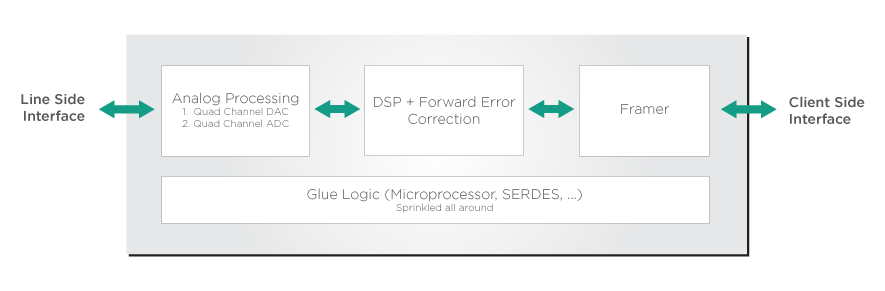
- Analog Processing: This engine segment focuses on converting signals between analog and digital formats. Digital data is composed of discrete values like 0s and 1s, but transmitting it through a coherent optical system requires converting it into an analog signal with continuous values. Meanwhile, a light signal received on the opposite end requires conversion from analog into digital format.
- Digital Signal Processing: This is the actual digital processing. As explained previously, this block encodes the digital data into the different properties of a light signal. It also decodes this data when the light signal is received.
- Forward Error Correction (FEC): FEC makes the coherent link much more tolerant to noise than a direct detect system and enables much longer reach and higher capacity. Thanks to FEC, coherent links can handle bit error rates that are literally a million times higher than a typical direct detect link. FEC algorithms allow the electronic engine to enhance the link performance without changing the hardware. This enhancement is analogous to imaging cameras: image processing algorithms allow the lenses inside your phone camera to produce a higher-quality image.
- Framer: While a typical electric signal sent through a network uses the Ethernet frame format, the optical signal uses the Optical Transport Network (OTN) format. The framer block performs this conversion. We should note that an increasingly popular solution in communication systems is to send Ethernet frames directly over the optical signal (a solution called optical Ethernet). However, many legacy optical communication systems still use the OTN format, so electronic engines should always have the option to convert between OTN and Ethernet frames.
- Glue Logic: This block consists of the electronic circuitry needed to interface all the different blocks of the electronic engine. This includes the microprocessor that drives the electronic engine and the serializer-deserializer (SERDES) circuit. Since coherent systems only have four channels, the SERDES circuit converts parallel data streams into a single serial stream that can be transmitted over one of these channels. The opposite conversion (serial-to-parallel) occurs when the signal is received.
We must highlight that each of these blocks has its own specialized circuitry and algorithms, so each is a separate piece of intellectual property. Therefore, developing the entire electronic engine requires ownership or access to each of these intellectual properties.
So What’s Inside the Actual DSP Block?
Having clarified first all the different parts of a transceiver’s electronic engine, we can now talk more specifically about the actual DSP block that encodes/decodes the data and compensates for distortions and impairments in the optical fiber. We will describe some of the critical functions of the DSP in the order in which they happen during signal transmission. Receiving the signal would require these functions to occur in the opposite order, as shown in the diagram below.
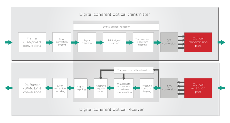
- Signal Mapping: This is where the encoding/decoding magic happens. The DSP maps the data signal into the different phases of the light signal—the in-phase components and the quadrature components—and the two different polarizations (x- and y- polarizations). When receiving the signal, the DSP will perform the inverse process, taking the information from the phase and polarization and mapping it into a stream of bits. The whole process of encoding and decoding data into different phases of light is known as quadrature modulation. Explaining quadrature modulation in detail goes beyond the scope of this article, so if you want to know more about it, please read the following article.
- Pilot Signal Insertion: The pilot signal is transmitted over the communication systems to estimate the status of the transmission path. It makes it easier (and thus more energy-efficient) for the receiver end to decode data from the phase and polarization of the light signal.
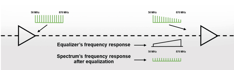
- Adaptive Equalization: This function happens when receiving the signal. The fiber channel adds several distortions to the light signal (more on that later) that change the signal’s frequency spectrum from what was initially intended. Just as with an audio equalizer, the purpose of this equalizer is to change specific frequencies of the signal to compensate for the distortions and bring the signal spectrum back to what was initially intended.
- Dispersion and Nonlinear Compensation: This function happens when receiving the signal. The quality of the light signal degrades when traveling through an optical fiber by a process called dispersion. The same phenomenon happens when a prism splits white light into several colors. The fiber also adds other distortions due to nonlinear optical effects. These effects get worse as the input power of the light signal increases, leading to a trade-off. You might want more power to transmit over longer distances, but the nonlinear distortions also become larger, which beats the point of using more power. The DSP performs several operations on the light signal that try to offset these dispersion and nonlinear distortions.
- Spectrum Shaping: Communication systems must be efficient in all senses, so they must transmit as much signal as possible within a limited number of frequencies. Spectrum shaping is a process that uses a digital filter to narrow down the signal to the smallest possible frequency bandwidth and achieve this efficiency.
When transmitting, the signal goes through the digital-to-analog conversion after this whole DSP sequence. When receiving the signal, it goes through the inverse analog-to-digital conversation and then through the DSP sequence.
Recent Advances and Challenges in DSPs
This is an oversimplification, but we can broadly classify the two critical areas of improvement for DSPs into two categories.
Transmission Reach and Efficiency
The entire field of communication technology can arguably be summarized with a single question: how can we transmit more information into a single frequency-limited signal over the longest possible distance?
DSP developers have many tools in their kit to answer this question. For example, they can transmit more data using more states in their quadrature-amplitude modulation process. The simplest kind of QAM (4-QAM) uses four different states (usually called constellation points), combining two different intensity levels and two different phases of light.
By using more intensity levels and phases, more bits can be transmitted in one go. State-of-the-art commercially available 400ZR transceivers typically use 16-QAM, with sixteen different constellation points that arise from combining four different intensity levels and four phases. However, this increased transmission capacity comes at a price: a signal with more modulation orders is more susceptible to noise and distortions. That’s why these transceivers can transmit 400Gbps over 100km but not over 1000km.
One of the most remarkable recent advances in DSPs to increase the reach of light signals is probabilistic constellation shaping (PCS). In the typical 16-QAM modulation used in coherent transceivers, each constellation point has the same probability of being used. This is inefficient since the outer constellation points that require more power have the same probability as the inner constellation points that require lower power.
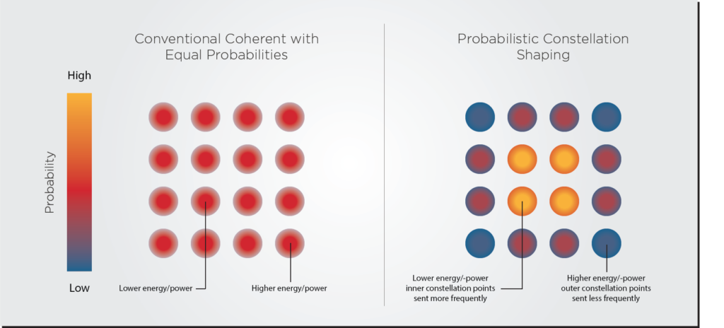
PCS uses the low-power inner constellation points more frequently, and the outer constellation points less frequently, as shown in Figure 5. This feature provides many benefits, including improved tolerance to distortions and easier system optimization to specific bit transmission requirements. If you want to know more about it, please read the explainers here and here.
Energy Efficiency
Increases in transmission reach and efficiency must be balanced with power consumption and thermal management. Energy efficiency is the biggest obstacle in the roadmap to scale high-speed coherent transceivers into Terabit speeds.
Over the last two decades, power ratings for pluggable modules have increased as we moved from direct detection to more power-hungry coherent transmission: from 2W for SFP modules to 3.5 W for QSFP modules and now to 14W for QSSFP-DD and 21.1W for OSFP form factors. Rockley Photonics researchers estimate that a future electronic switch filled with 800G modules would draw around 1 kW of power just for the optical modules.
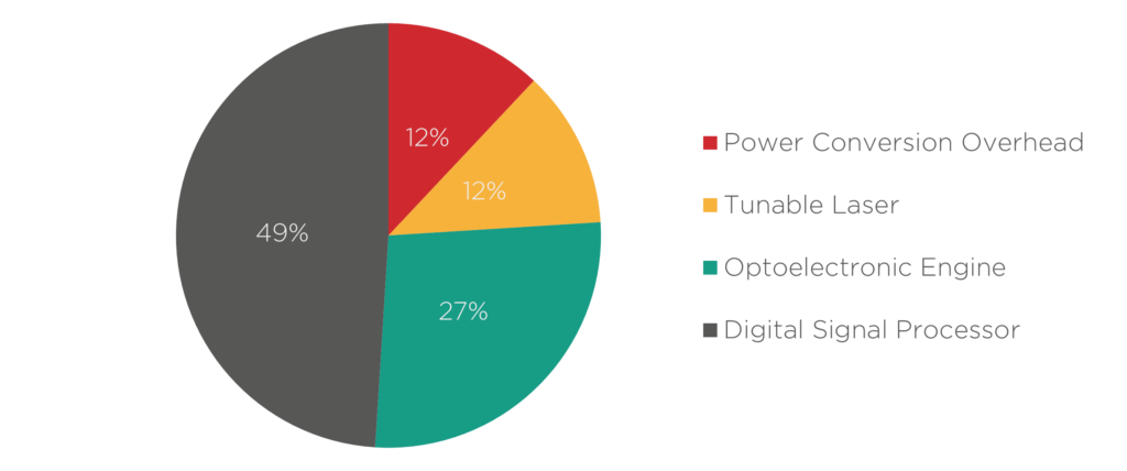
Around 50% of a coherent transceiver’s power consumption goes into the DSP chip. Scaling to higher bandwidths leads to even more losses and energy consumption from the DSP chip, and its radiofrequency (RF) interconnects with the optical engine. DSP chips must therefore be adaptable and smart, using the least amount of energy to encode/decode information. You can learn more about this subject in one of our previous articles. The interconnects with the optical engine are another area that can see further optimization, and we discuss these improvements in our article about optoelectronic co-design.
Takeaways
In summary, DSPs are the heart of coherent communication systems. They not only encode/decode data into the three properties of a light signal (amplitude, phase, polarization) but also handle error correction, analog-digital conversation, Ethernet framing, and compensation of dispersion and nonlinear distortion. And with every passing generation, they are assigned more advanced functions such as probabilistic constellation shaping.
There are still many challenges ahead to improve DSPs and make them transmit even more bits in more energy-efficient ways. Now that EFFECT Photonics has incorporated talent and intellectual property from Viasat’s Coherent DSP team, we hope to contribute to this ongoing research and development and make transceivers faster and more sustainable than ever.