
Hot Topics, Cool Solutions: Thermal Management in Optical Transceivers
In a world of optical access networks, where data speeds soar and connectivity reigns supreme, the thermal management of optical transceivers is a crucial factor that is sometimes under-discussed. As the demand for higher speeds grows, the heat generated by optical devices poses increasing challenges. Without proper thermal management, this excessive heat can lead to performance degradation, reduced reliability, and lifespan, increasing optical equipment’s capital and operating expenditures.
By reducing footprints, co-designing optics and electronics for greater efficiency, and adhering to industry standards, operators can reduce the impact of heat-related issues.
Integration Reduces Heat Losses
The best way to manage heat is to produce less of it in the first place. Optical transceivers consist of various optical and electronic components, including lasers, photodiodes, modulators, electrical drivers and converters, and even digital signal processors. Each of these elements generates heat as a byproduct of their operation. However, photonic and electronic technology advances have enabled greater device integration, resulting in smaller form factors and reduced power consumption.
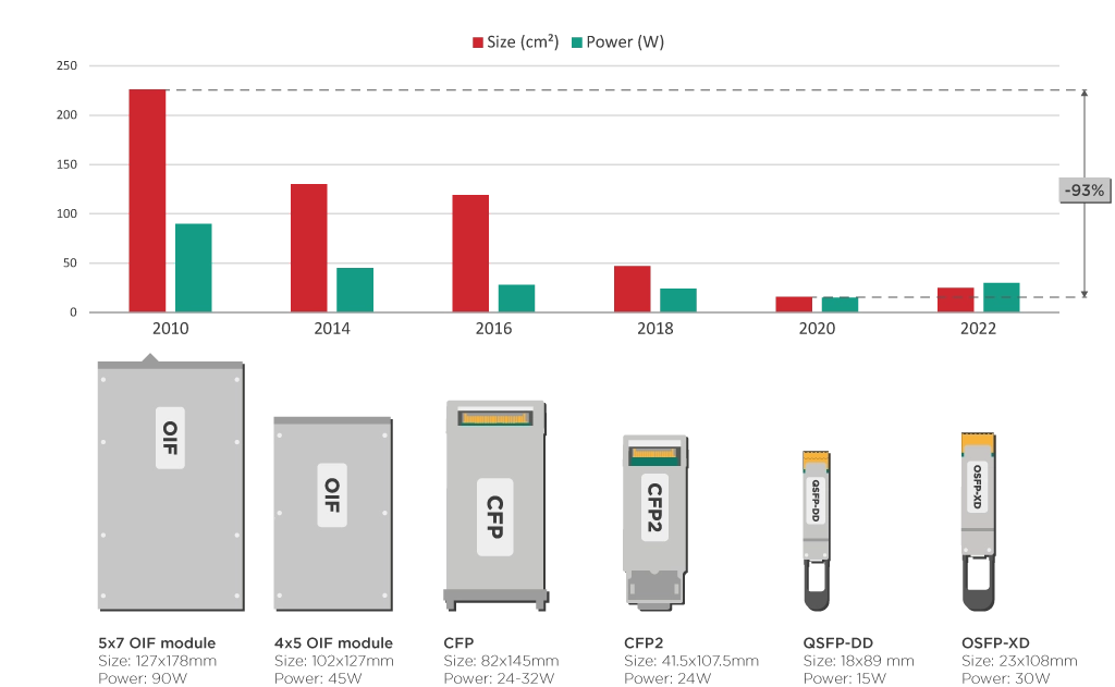
For example, over the last decade, coherent optical systems have been miniaturized from big, expensive line cards to small pluggables the size of a large USB stick. These compact transceivers with highly integrated optics and electronics have shorter interconnections, fewer losses, and more elements per chip area. These features all lead to a reduced power consumption over the last decade, as shown in the figure below.
Co-design for Energy Efficiency
Co-designing the transceiver’s optics and electronics is a great tool for achieving optimal thermal management. Co-designing the DSP chip alongside the photonic integrated circuit (PIC) can lead to a much better fit between these components. A co-design approach helps identify in greater detail the trade-offs between various parameters in the DSP and PIC and thus improve system-level performance and efficiency.
To illustrate the impact of co-designing PIC and DSP, let’s look at an example. A PIC and a standard platform-agnostic DSP typically operate with signals of differing intensities, so they need some RF analog electronic components to “talk” to each other. This signal power conversion overhead constitutes roughly 2-3 Watts or about 10-15% of transceiver power consumption.
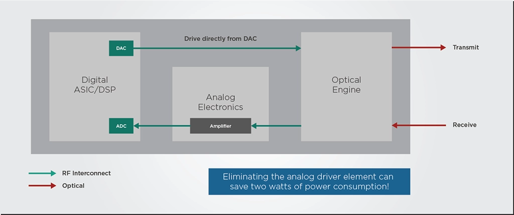
However, the modulator of an InP PIC can run at a lower voltage than a silicon modulator. If this InP PIC and the DSP are designed and optimized together instead of using a standard DSP, the PIC could be designed to run at a voltage compatible with the DSP’s signal output. This way, the optimized DSP could drive the PIC directly without needing the RF analog driver, doing away with most of the power conversion overhead we discussed previously.
Follow Best Practices and Standards
Effective thermal management also means following the industry’s best practices and standards. These standards ensure optical transceivers’ interoperability, reliability, and performance. Two common ratings that will condition the thermal design of optical transceivers are commercial (C-temp) and industrial (I-temp) ratings.
Commercial temperature (C-temp) transceivers are designed to operate from 0°C to 70°C. These transceivers suit the controlled environments of data center and network provider equipment rooms. These rooms have active temperature control, cooling systems, filters for dust and other particulates, airlocks, and humidity control. On the other hand, industrial temperature (I-temp) transceivers are designed to withstand more extreme temperature ranges, typically from -40°C to 85°C. These transceivers are essential for deployments in outdoor environments or locations with harsh operating conditions. It could be at the top of an antenna, on mountain ranges, inside traffic tunnels, or in the harsh winters of Northern Europe.
| Temperature Standard | Temperature Range (°C) | |
| Min | Max | |
| Commercial (C-temp) | 0 | 70 |
| Extended (E-temp) | -20 | 85 |
| Industrial (I-temp) | -40 | 85 |
| Automotive / Full Military | -40 | 125 |
Operators can ensure the transceivers’ longevity and reliability by selecting the appropriate temperature rating based on the deployment environment and application. On the side, of the component manufacturer, the temperature rating will have a significant impact on the transceiver’s design and testing. For example, making an I-temp transceiver means that every internal component—the integrated circuits, lasers, photodetectors—must also be I-temp compliant.
Takeaways
Operators can overcome heat-related challenges and ensure optimal performance by reducing heat generation through device integration, co-designing optics and electronics, and adhering to industry standards. By addressing these thermal management issues, network operators can maintain efficient and reliable connectivity and contribute to the seamless functioning of optical networks in the digital age.