Fit for Platform DSPs
Over the last two decades, power ratings for pluggable modules have increased as we moved from direct detection to more power-hungry coherent transmission: from 2W for SFP modules to 3.5 W for QSFP modules and now to 14W for QSSFP-DD and 21.1W for OSFP form factors. Rockley Photonics researchers estimate that a future electronic switch filled with 800G modules would draw around 1 kW of power just for the optical modules.
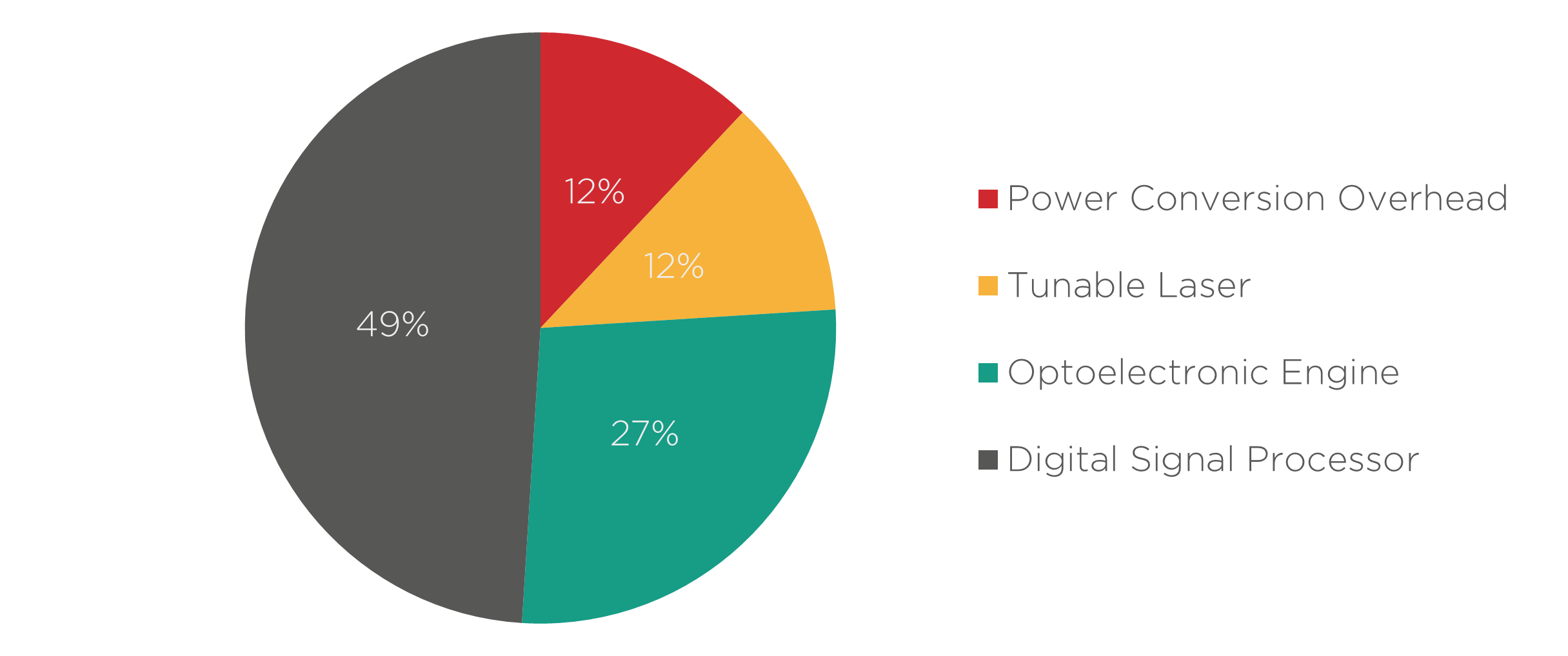
Around 50% of a coherent transceiver’s power consumption goes into the digital signal processing (DSP) chip that also performs the functions of clock data recovery (CDR), optical-electrical gear-boxing, and lane switching. Scaling to higher bandwidths leads to even more losses and energy consumption from the DSP chip and its radiofrequency (RF) interconnects with the optical engine.
One way to reduce transceiver power consumption requires designing DSPs that take advantage of the material platform of their optical engine. In this article, we will elaborate on what that means for the Indium Phosphide platform.
A Jack of All Trades but a Master of None
Transceiver developers often source their DSP, laser, and optical engine from different suppliers, so all these chips are designed separately from each other. This setup reduces the time to market and simplifies the research and design processes but comes with trade-offs in performance and power consumption.
In such cases, the DSP is like a Swiss army knife: a jack of all trades designed for different kinds of optical engines but a master of none. For example, current DSPs are designed to be agnostic to the material platform of the photonic integrated circuit (PIC) they are connected to, which can be Indium Phosphide (InP) or Silicon. Thus, they do not exploit the intrinsic advantages of these material platforms. Co-designing the DSP chip alongside the PIC can lead to a much better fit between these components.
Co-Designing with Indium Phosphide PICs for Power Efficiency
To illustrate the impact of co-designing PIC and DSP, let’s look at an example. A PIC and a standard platform-agnostic DSP typically operate with signals of differing intensities, so they need some RF analog electronic components to “talk” to each other. This signal power conversion overhead constitutes roughly 2-3 Watts or about 10-15% of transceiver power consumption.
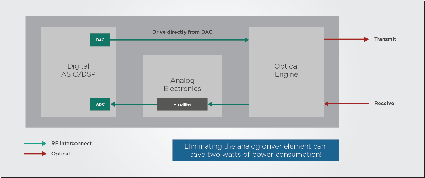
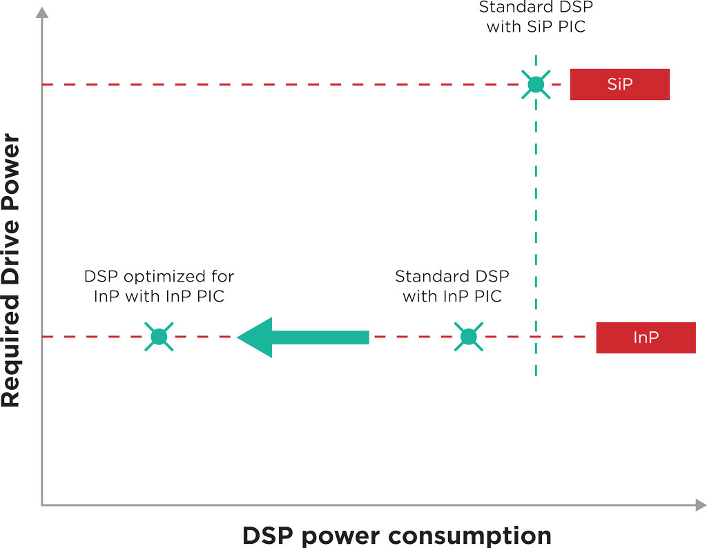
However, the modulator of an InP PIC can run at a lower voltage than a silicon modulator. If this InP PIC and the DSP are designed and optimized together instead of using a standard DSP, the PIC could be designed to run at a voltage compatible with the DSP’s signal output. This way, the optimized DSP could drive the PIC directly without needing the RF analog driver, doing away with most of the power conversion overhead we discussed previously.
Additionally, the optimized DSP could also be programmed to do some additional signal conditioning that minimizes the nonlinear optical effects of the InP material, which can reduce noise and improve performance.
Taking Advantage of Active Components in the InP Platform
Russell Fuerst, EFFECT Photonics’ Vice-President of Digital Signal Processing, gave us an interesting insight about designing for the InP platform in a previous interview:
When we started doing coherent DSP designs for optical communication over a decade ago, we pulled many solutions from the RF wireless and satellite communications space into our initial designs. Still, we couldn’t bring all those solutions to the optical markets.
However, when you get more of the InP active components involved, some of those solutions can finally be brought over and utilized. They were not used before in our designs for silicon photonics because silicon is not an active medium and lacked the performance to exploit these advanced techniques.
For example, the fact that the DSP could control laser and modulator components on the InP can lead to some interesting manipulations of light signals. A DSP that can control these components directly could generate proprietary waveforms or use non-standard constellation and modulation schemes that can boost the performance of a coherent transceiver and increase the capacity of the link.
Takeaways
The biggest problem for DSP designers is still improving performance while reducing power use. This problem can be solved by finding ways to integrate the DSP more deeply with the InP platform, such as letting the DSP control the laser and modulator directly to develop new waveform shaping and modulation schemes. Because the InP platforms have active components, DSP designers can also import more solutions from the RF wireless space.