
Co-Designing Optics and Electronics for Versatile and Green Transceivers
Network and data center operators need fast and affordable pluggable transceivers that perform well enough to cover a wide range of link lengths. However, power consumption and thermal management are the big obstacles in the roadmap to scale high-speed transceivers into Terabit speeds.
Over the last two decades, power ratings for pluggable modules have increased as we moved from direct detection to more power-hungry coherent transmission: from 2W for SFP modules to 3.5 W for QSFP modules and now to 14W for QSSFP-DD and 21.1W for OSFP form factors. Rockley Photonics researchers estimate that a future electronic switch filled with 800G modules would draw around 1 kW of power just for the optical modules.
Around 50% of a coherent transceiver’s power consumption goes into the digital signal processing (DSP) chip that also performs the functions of clock data recovery (CDR), optical-electrical gear-boxing, and lane switching. Scaling to higher bandwidths leads to even more losses and energy consumption from the DSP chip and its radiofrequency (RF) interconnects with the optical engine.

Thus, a great incentive exists to optimize the interface between the module’s DSP chip and the optical engine to make the transceiver more energy efficient. This need for optimization and efficiency makes co-designing the optical and electronic systems of the transceiver more important than ever.
Co-Designing the Optimal DSP
Coherent DSPs are already application-specific integrated circuits (ASICs), but they could fit their respective optical engines and use cases even more tightly. Transceiver developers often source their DSP, laser, and optical engine from different suppliers, so all these chips are designed separately from each other. This setup reduces the time to market and simplifies the research and design processes but comes with trade-offs in performance and power consumption.
In such cases, the DSP is like a Swiss army knife: a jack of all trades designed for different kinds of PIC but a master of none. For example, many 400ZR+ transceivers used for telecom metro and long-haul applications are using the same DSPs as 400ZR transceivers used for much shorter data center interconnects. Given the ever-increasing demand for capacity and the need for sustainability both as financial and social responsibility, transceiver developers are increasingly in need of a steak knife rather than a Swiss army knife.
Co-designing the DSP chip alongside the photonic integrated circuit (PIC) can lead to a much better fit between these components. A co-design approach helps identify in greater detail the trade-offs between various parameters in the DSP and PIC and thus improve system-level performance optimization. A DSP optimized for a specific optical engine and application could save up to a couple of Watts of power compared to the usual transceiver and DSP designs.
Co-designing DSP Interfaces for Power Efficiency
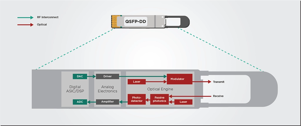
Since the optical engine and DSP operate with signals of differing intensities, they need some analog electronic components to “talk” to each other. On the transmit side, the electronic driver block takes signals from the DSP, converts them to a higher voltage, and drives the optical engine. On the receive side, a trans-impedance amplifier (TIA) block will boost the weak signal captured by the optical detector so that the DSP can more easily process it. This signal power conversion overhead constitutes roughly 10-15% of transceiver power consumption, as shown in Figure 1.
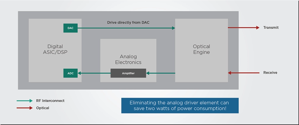
Co-designing the DSP and PIC could enable ways to decrease this power conversion overhead. For example, the modulator of the optical engine could be designed to run at a lower voltage that is more compatible with the signal output of the DSP. This way, the DSP could drive the optical engine directly without the need for the analog electronic driver. Such a setup could save roughly two watts of power consumption!
Co-design is also vital to optimize the transceiver layout floorplan. This plan must consider the power dissipation of all transceiver building blocks to avoid hot spots and thermal interference from the DSP to the highly thermally sensitive PIC. The positioning of all bond pads and interfaces is also very important for signal and power integrity, requiring a co-design with the package and substrate.
During this floorplan development, the RF interconnections between the DSP and PIC can be made as short as possible. These optimized RF interconnects reduce the optical and thermal losses in the transceiver package and will reduce the power consumption of the analog electronic driver and amplifier.
Co-Designing Fit-For-Purpose DSPs and PICs
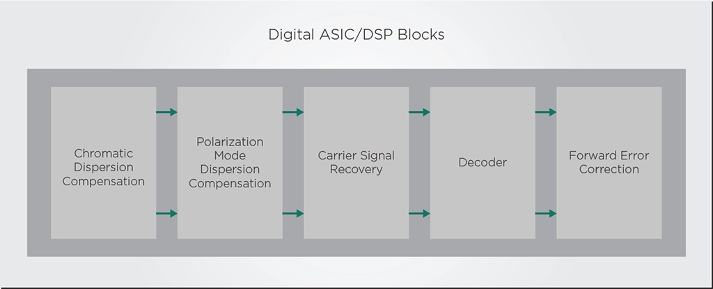
As shown in Figure 4, a DSP chip contains a sequence of processing blocks that compensate for different transmission issues in the fiber and then recover, decode, and error-correct the data streams. Different applications might require slightly different layouts of the DSP or might not need some processing blocks.
For example, full DSP compensation might be required for long links that span several hundreds of kilometers, but a shorter link might not require all the DSP functions. In these cases, a transceiver could turn off or reduce certain DSP functions—such as chromatic dispersion compensation—to save power. These power-saving features could be particularly useful for the cases of shorter data center interconnect links (DCI). On the optical engine side, the laser might not require a high power to transmit over this shorter DCI link so the amplifier functions could shut down. Co-designing the DSP and PIC allows a transceiver developer to mix and match these different energy-saving features to achieve the lowest possible power for a specific application.
Takeaways
Power consumption has become the big barrier that prevents pluggable transceivers from scaling up to 800G and Terabit speeds. Overcoming this barrier requires a tighter fit between the optics and electronics of the transceiver, especially when it comes to the interface between the optical engine and the electronic DSP. By co-designing the optical engine and the electronic DSP, transceiver developers could avoid the need for an external electrical driver and reduce transceiver power consumption by 10-15%. A co-design approach can also make it easier to design fit-for-purpose transceivers that implement power-saving features tailored to specific application cases.
The benefits of this co-design approach led EFFECT Photonics to incorporate talent and intellectual property from Viasat’s Coherent DSP team. With this merger, EFFECT Photonics aims to co-design our Optical System-On-Chip with the DSP to develop fit-for-purpose transceivers that are more energy-efficient than ever before.